deutsch     english    français     Print


5.3 CONTROLLING AND REGULATING


INTRODUCTION


When working with machines, which also include robots, we often face the problem of controlling them in a way that a particular measured variable complies as well as possible with a predetermined value (the target value or set point). For example, the cruise control in a car should keep a predetermined speed even when the car drives on a slope or an incline. To do this, a control system with a sensor needs to determine the current speed (the actual value) and then adjust the power of the motor accordingly with an actuator, so in a way it needs to operate the gas pedal.

Other examples of technical regulation systems:

  • Maintaining the temperature of a refrigerator (thermostat control)
  • Keeping an airplane on a specific course (autopilot)
  • Maintaining the fill level of a liquid reservoir (e.g. toilet flushing)

Many human activities can be considered as regulatory processes. Some examples:

  • Steering a car so that it stays on the road
  • Working just as much as you need to barely pass your degree
  • Maintaining your balance while standing on one foot

PROGRAMMING CONCEPTS: Control system, actual value, target value, measurement error


SELF-DRIVING CAR


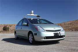
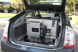
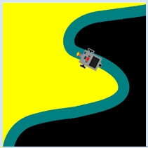
Driving is a complex control process with many input signals that affect the driver not only visually, but also tactually (forces on the body). The mental processing of these signals leads to the driver's behavior (rotation of the steering wheel, pressing the pedals, etc.).

In the future,vehicles will be able to drive themselves without a human, even in complex traffic situations. Several research groups around the world are working on this problem, and it is possible that you might even participate in this interesting research at some point. You can already try out some of your skills here in a highly simplified situation.


Your task is to guide the robot, which is equipped with a chassis and a light sensor that can measure the brightness of the underlying layer, along a green road that is bounded by a yellow and a black area. When on the green part, the sensor signals a middle light value, on the yellow part a large light value, and a small one on the black part. It is the task of the control system to create a control signal for the motors from the measured light values, so that the robot is able to move along the road as well as possible.


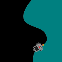
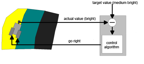
Schematically, you can represent this process in a control loop. The light sensor measures the current light value (actual value) and delivers it to the controller, which compares it to the desired value (target value) on the green road. The controller calculates the control quantity for the chassis, meaning that the two motors are switched accordingly, using a control algorithm invented by you, which takes decisions based on the difference between the target and actual values.


Control loop

As you can see, this scheme is indeed a "loop", from the vehicle sensor to the regulatory system, and then back again to the vehicle engines.

Before you can write the program, you need to know the light values that are provided by the sensor for the yellow, green, and black areas. To figure this out, write a small test program that displays the measured values on the console or the display. In the real mode, you do not have to move the robot. Instead, you can just place it on the corresponding area. In the simulation mode, you move through the areas colored accordingly (this process is called calibration). Use the NXT Light Sensor for the NXT and the EV3 Color Sensor for the EV3.


from simrobot import *
#from nxtrobot import *
#from ev3robot import *

RobotContext.setStartPosition(250, 490)
RobotContext.useBackground("sprites/roadtest.gif")

robot = LegoRobot()
gear = Gear()
robot.addPart(gear)
ls = LightSensor(SensorPort.S3)
robot.addPart(ls)
ls.activate(True)
gear.forward()

while not robot.isEscapeHit():
    v = ls.getValue()
    print(v)
    Tools.delay(100)
robot.exit()
Highlight program code (Ctrl+C to copy, Ctrl+V to paste)

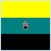
You are using an obvious control algorithm in your program: If the actual value is larger than the target value, the vehicle is in the yellow area and has to make a right turn. If the actual value is less than the target value, the vehicle is in the black area and has to make a left turn. Otherwise, it can move straight ahead.

from simrobot import *
#from nxtrobot import *
#from ev3robot import *

RobotContext.setStartPosition(50, 490)
RobotContext.useBackground("sprites/road.gif")
  
robot = LegoRobot()
gear = Gear()
robot.addPart(gear)
ls = LightSensor(SensorPort.S3)
robot.addPart(ls)
ls.activate(True)
gear.forward()
nominal = 501

while not robot.isEscapeHit():
    actual = ls.getValue()
    if actual == nominal:
        gear.forward()
    elif actual < nominal:
        gear.leftArc(0.1)
    elif actual > nominal:
        gear.rightArc(0.1)

robot.exit()
Highlight program code (Ctrl+C to copy, Ctrl+V to paste)


MEMO


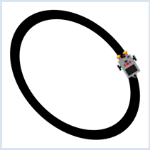
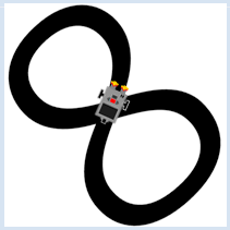
The regulation works well in the simulation mode, but not in the real mode. You probably realize why this is: The measured values of the sensor vary, even when the sensor is located on an uniformly colored area. But then this can be expected since the brightness, even on the same surface, never remains exactly the same due to the differences in lighting, and also because of measurement errors from the sensor. Try to find a solution for this problem! The curve radius at leftArc() or rightArc() is a sensitive parameter. A smaller value leads to smaller "outliers" away from the street, but to an unsettled oscillating behavior [more...Controller oscillations are a typical error of control processes and can lead to failure of the control (instability)], while a larger value results in a calmer movement, but with less precise guidance on the street. Confirm this through some trials with varied curve radiuses.


EXERCISES


1.

Move along a black-green edge with a light sensor. Use the following RobotContext for the simulation mode:

RobotContext.useBackground("sprites/edge.gif")
RobotContext.setStartPosition(250, 490)


2.

Move along a circular path with two light sensors.

Use the following RobotContext in the simulation mode:

RobotContext.useBackground("sprites/roundpath.gif")
RobotContext.setStartPosition(250, 250)
RobotContext.setStartDirection(-90)

Change the starting position and direction so that the robot begins on the track.


3.

Ride on a roller coaster with two light sensors. Use the background track.gif in the simulation mode.

RobotContext.useBackground("sprites/track.gif")